Content Moved!
Containers
Container
Application run business. Application run on servers. Earlier, 1 application on 1 server. Later, Hyper-visor came. Run multiple Apps on 1 server.
Issues with Hyper-visor model:
- we create VM (slices of physical server hardware) – to run app
- Each VM needs own OS
- licence of OS and operational baggage (patch/antivirus/admin) for each VM
Container: no VM and no extra OS that we have to boot before starting our app. All app sharing single OS…. more space for containers… fast spin up of app
- what if we can use just 1 OS and can have containers (1 container = 1 App)
- Slice Operating system, into containers
What we need
- A OS – say ubuntu machine with docker engine installed..note: ip address
- Docker image: like OVF … virtual image template… container with app
- commands
- docker images – list images
- docker run -d –name web -p 8080:8080 docker_image_location
- docker stop web
- docker start web
Docker
Docker is to container like VMWare is to hypervisor.
Docker Inc. — provided dotCloud (PaaS provide developer platform on top of AWS) — “dock worker” turn into “docker”…. turn from service company to container company……
Docker project — belongs to community. is open source. Docker engine is core technology – build and manage image, start and stop container. The orchestration, security, registry are plugged into it. Core Docker component are written in Go.
Docker Hub — the public docker registry — docker images
OCI – governance council – open container initiative – for standard about container format and container runtime. Vendor and
CoreOS – own container tech – runtime rkt, container format specification- appc
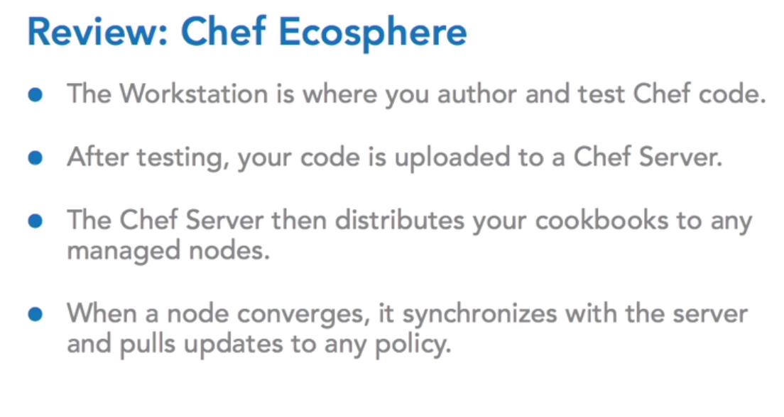
Chef

Nodes do the heavy lifting to configure themselves – covergence
Node run ohio tool to collect its info and pass that info to chef server
Workstation installation
Install the latest version version of the Chef Development Kit for your Operating System from:
https://downloads.chef.io/chef-dk/
The toolkit is installed using something called the omnibus installer. What’s important for you to understand is that the Chef development kit is installed in an embedded context. What this means is that, if you, for instance, have Ruby installed globally on your machine, the Chef development kit will not conflict with any other installed tools.

This commands will be available:
chef –version
chef-client –version
knife –version
ohai –version
berks –version
kitchen –version
foodcritic –version
cookstyle –version
Install Git from: https://git-scm.com/downloads/
Text editor: Atom/Visual studio/vi/sublime
ARCHITECT 1 (no chef server) – write 1st recipe but it is not a real life architect
Test RUN A RECIPE: VAGRANT BOX AS WORKSTATION AND CHEF-CLIENT
VirtualBox and VAGRANT, using centOS 7.2 box – can be your Workstation (install ChefDK)

# These commands are meant to be run from your LOCAL machine
vagrant --version
 VBoxManage --version

vagrant box add bento/centos-7.2 --provider=virtualbox

vagrant init bento/centos-7.2 :Create Vagrant file use for provisioning VM

vagrant up :Spin up VM using Vagarat file

vagrant status :gives you name of VM running, default VM name is 'default'

vagrant ssh [default]
# The next set of commands are run INSIDE of the vagrant instance
# install the ChefDK
curl https://omnitruck.chef.io/install.sh | sudo bash -s -- -P chefdk -c stable -v 0.18.30
chef –version
# install your text editor of choice! vim, emacs, or nano
sudo yum install vim -y
sudo yum install emacs -y
sudo yum install nano -y
# open your first recipe

vi hello.rb
 # content of ~/hello.rb

file '/hello.txt' do
 content 'Hello, world!'
 end
# run this file means run chef client ( we don’t have chef -server yet, so that instead of chef-client to grab instructions from server, we are going to use the file ‘hello.rb’ as instructions for chef-client)
cat /hello.txt :check this file exist?
sudo chef-client --local-mode hello.rb
cat /hello.txt :confirm this file exist after convergence
REAL ARCHITECT
Resource :
manage a particular system component; statement of configuration policy; it describes the desired state of an element of our infrastructure and steps needed to bring that item to the desired state
Recipe : is filled with chef resources. Any built-in chef resource also ensures idem potency ( means check state, only run is not in the desired state)
examples:
package ‘httpd’ do
action :install
end
service ‘ntp’ do
action [ :enable, :start]
end
file ‘/etc/motd’ do
content ‘i am message of day’
end
type_of_resource 'name_of_resource' do

  Properties

end
If you’re working with a file or a directory, for example, the name of the resource is also the path to that component. When working with a service, it would typically be the name used to configure it manually such as httpd or apache two. Notice that after we’ve declared the type and name of the resource, we then define what the content of the file should be. The content keyword is called a property.
Each built-in Chef resource has a list of properties that can be configured on that component.For files you could think of the permissions on a file as other properties that could be defined.For packages you might think of the installation directory for the package, or the version that should be installed, as properties. It’s often said that resources take action with the defined properties. In order to place a resource in the desired state that we define with properties, we take action on that resource.
Action is always taken on a resource whether it is defined or not. In this slide you can see that there is no action defined. This is going to cause the chef client to take the default action for this resource. Default actions usually follow what’s called the principle of least surprise.
Learn about resources: https://docs.chef.io/resources.html
Cookbook:
fundamental unit of configuration and policy distribution
This means that once we’re working with a Chef server we won’t be distributing individual recipes to servers, we’ll be distributing cookbooks.
These cookbooks contain all the instructions on how to use the recipes that come with it and any supporting components your recipes might need to function. Cookbooks can generally be thought of as containers for our recipes.
When we author cookbooks, it’s important to think about it as a standalone unit that defines a scenario and contains all the components needed to support that scenario. For example, a MySQL cookbook would contain all the instructions on how to install and configure a database.
# These commands are meant to be run from inside the VAGRANT instance, after running ‘vagrant ssh’
chef --help
 chef generate --help

mkdir cookbooks
 chef generate cookbook cookbooks/apache

sudo yum install tree -y
 tree


you’ll notice there’s always going to be a default recipe. The default recipe is used to set up a default configuration for this cookbook.

spec: unit test
test: integration test
This is assuming that you have installed Git for version control. If you’ve installed Git, when you run the chef generate cookbook command, you’ll see that it creates a .git directory. This allows you to actually work with version control

Configure apache cookbook
chef generate cookbook cookbooks/apache

chef generate recipe cookbooks/apache server

vi cookbooks/apache/recipe/server.rb
package 'httpd'

file '/var/www/html/index.html' do
 content '<h1>Hello, World!</h1>'
 end

service 'httpd' do
 action [:enable, :start]
 end
#Apply
sudo chef-client --local-mode server.rb
# Test
curl localhost
should return Hello world page if apache service is running


If we execute the chef-client without giving it a cookbook, it might not know where to find some of those advanced components, like templates,
concept of the run list

#running without runlist - specify recipe
sudo chef-client --local-mode server.rb#
running an example in local mode using runlist
sudo chef-client --local-mode -runlist "recipe[apache::server]"
sudo chef-client -z -r "recipe[apache::server]"
in above command: dafault recipe will be called if no recipe specified
Call other recipe: include_recipe “cookbook::recipe”
RESOURCES:
Chef resources are not pure Ruby code and cannot be run inside of a Ruby interpreter like Ruby IRB.
It’s important to understand that only the Chef client can interpret Chef resources. This is important because we often say that it’s not important to actually understand Ruby at a deep level to use Chef. And this is entirely true. What is important is understanding Chef resources.
Most common resources
package
template
service
file

on docs.chef --> search ruby -- open chef style guide
(this is how much ruby u need), imp to know resources
DEAL WITH HOST SPECIFIC DETAIL IS NEEDED
hostname
hostname -I (ip address on centos)
cat /proc/meminfo
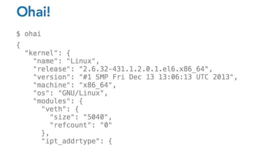
Gather host-specific details IN REALTIME
OHAI
Ohai is the tool that will actually gather host-specific details for you. And it will present them to you in json. This is, quite literally, a command line tool, called Ohai. O-h-a-i.
And you can run it anywhere that you have the Chef client or the chef development kit installed.
Cloud
Infrastructure , Platform or Software as a Service

SCALING – Elasticity – loose coupling


Horizontal scaling = scaling OUT/IN Vertical Scaling = Scaling UP/Down
And On Demanding: Auto Scaling
However, application must be built in a scalable way in order to use a scalable infrastructure
trigger : time, based on known event, monitor metric and scale based on threshold
CLOUD VS ON-PREMISE SPECIFICATION
Exact replica may not be there. Think for alternative
ElastiCache = RAM
DB Server = RDS / Dynamo DB
Any constraints are just the difference between scalability and non-scalability
Everything fails, all the time
The idea here is that while failure should be expected within the individual components of an application, the overall system can be architected to prevent application failure.
Expecting parts of the system to fail will drive an architecture that leads to the building of an overall system that won’t fail.
Avoid single point of failure. example single serve instance hosting both web and database software

Below, still single point of failure in load balancer and database server

Below, no single point of failure. Scaling and redundancy are included

Avoiding single point of failure not only relevant to hardware level but includes consideration at network and software level as well. Thus, needs to be incorporated in application design.
Moreover, considerations must be given to how the fail over happens.
Loose coupling
web server need to know which app server to connect to, it is called tight coupling between components. if web server connect to load balancer which will allow the connection to be distributed to any number of app servers then dependency between web and app server is removed and thus the coupling is loosened

AWS services
When possible, consider using serverless architectures with an AWS in your application design.
Using services like S3 and CloudFront to host websites means not worrying about web servers at all. And services like Lambda to execute code eliminates the need for app servers all together. Storage options such as DynamoDB and Elasticache also remove the need for server setup and configuration. Continuous monitoring of applications is also required to ensure optimal performance is maintained. Amazon CloudWatch helps with this. CloudWatch provides the ability to monitor application metrics and send notification alarms when thresholds are breached.
These alarms can trigger automated actions by integrating with other services such as Amazon Simple Queue Service, Amazon Simple Notification Service, and Amazon Lambda.
File storing data: Elastic block storage, which persists beyond the lifetimeof the underlying instance, and local storage, which will not survive termination of the instance on which it resides.
Security
The responsibility of security is shared between the Cloud provider and the Cloud customer. In general, the Cloud provider is responsible for the physical security of the buildings, the infrastructure, the equipment, and keeping different customers secure from each other.
On the other hand, the Cloud customer has to provide security at the network and at the application level, especially as it pertains to the application data. Data in motion needs to be protected as well. For example, when transmitting confidential information on the internet, a secure communication protocol, such as HTTP over SSL, should be used. A nice feature of Amazon’s elastic load balancer service is that security certificates can be managed directly on the load balancer.
All AWS services have an available API. To use this APIs, security credential called access keys are needed. The AWS access key has two parts to it, a public access key ID and a secret access key.
When using the API, the secret key is used in the request for authentication. Therefore, all API requests sent from the public internet should be sent over HTTPS. Rather than storing the secret key as part of an application code bundle, the application should be configured such that this value could be passed in as input during the launch of the application. Encrypting this information before sending should also be considered.

Rotate the access Keys Often
Another approach would be to make use of roles within the identity and access management service.Instances can be launched in an IAM role, and as such, the instance will have access to the credentials and permissions associated with that role.
IAM: access control: create users and manage permissions
Security groups = Firewalls
restrict to specific users, application and other resources that really require access
Cost
Use Consumption payment model of AWS.
Servers – cost by hour,
Autoscale – to meet demand,
use cost effective resource – correct EC2
AWS provides tools such as cost calculators, detailed billing reports, trusted advisor recommendations, and billing alerts to help eliminate surprise bills, stay on top of spending, and make cost saving suggestions.
EC2 = Service that provides Server in Cloud
elastic IP address
allows for an easy remap of a public IP to any instance in the account.
Elastic IP addresses are static IP addresses designed for dynamic cloud computing. An elastic IP address is created at the account level and is not specific to a particular server instance.
Fail over gracefully using elastic IPs. Use elastic IPs to quickly remap and fail over to another set of servers so that web traffic is routed to the new servers.This works great for handling emergencies, but also works well for rolling out new versions of hardware and software.
Region
Regions are independent of one another, and there is no data replication between them. The customer can decide to launch services in more than one region. Regions can help with very strict high availability and disaster recovery requirements that specify the need for redundant systems located very far apart geographically. While it’s great to know that building a system spanning two regions is an option, most system requirements can be met while working within a single region.
Even within a region, geographical isolation can be achieved to meet high availability and disaster recovery needs. This is because each region consists of multiple locations called availability zones. Availability zones are distinct locations that are engineered to be insulated from failures from other availability zones
Availability zones = logical Data center (conceptually)
AMI – Amazon Machine image
Deploy on or several instances
An AMI typically includes the following. A template for the root volume for the instance, for example an operating system, an application server, and supporting application libraries. Launch permissions that control which AWS accounts can use the AMI to launch instances. A block device mapping that specifies the elastic block storage volumes to attach to the instance when it’s launched. Amazon EC2 provides a number of tools to make creating an AMI easy, including the AWS management console.
Elastic load Balancing
An Elastic Load Balancer in AWS is a component for balancing network traffic across multiple EC2 instances within multiple availability zones.


The Elastic Load Balancer, or ELB for short, has a few key characteristics. It can handle the routing and load-balancing of HTTP, HTTPS, and TCP traffic to your EC2 instance. It allows so it can determine whether or not the instances to which it’s routing traffic are healthy and should be used. It can automatically and dynamically grow and shrink with the demand patterns of an application.
When creating a new ELB, a single CNAME is also created to use for DNS configuration. An interesting thing about this single CNAME is that it does not change even as the ELB scaling is happening. Here is a representation of an ELB routing traffic to two availability zones. The single CNAME ELB component actually resolves round robin DNS to ELB IP addresses in each availability zone. As traffic increases, AWS adds IP addresses to the ELB’s DNS entry, and continues to round robin requests across the multiple ELBs and vice-versa.

ELBs are themselves load-balanced, and Amazon takes care of this for us.
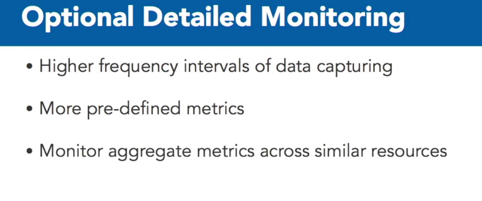
CloudWatch
CloudWatch is a resource and application monitoring and alert service that can help provide support for cloud-based applications.
It allows visibility into resource utilization performance and traffic load patterns.
CloudWatch for free with an option to pay mor.
Opting to pay a little more for detailed monitoring allows monitoring at higher frequency intervals than with the free plan.
EBS
Elastic Block Storage, or EBS for short, are storage resources that are created separately from EC2 instances.
EBS volumes are attached to EC2 instances. Once attached, they can be used like any other block device. Running a file system for data storage is a good example of using this type of storage device.

2 types of EBS volumes: Standard and provisioned IOPS volumes differ in price and performance


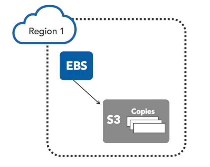
Snapshots can be used to create new volumes and new locations. Once on S3, snapshots can be copied to additional availability zones. They can be created across regions.

When creating a new volume from a snapshot, all of the snapshot data stored in S3 has to be transferred to this newly created volume. This takes time. However, the volume can be used right away. The restoring of new volumes from EBS snapshots implements a lazy loading approach. Any data initially being accessed will be prioritized during the transfer.
Snapshots are also useful for resizing volumes.
RDS
provides a way to set up, operate, and scale a relational database in the cloud.
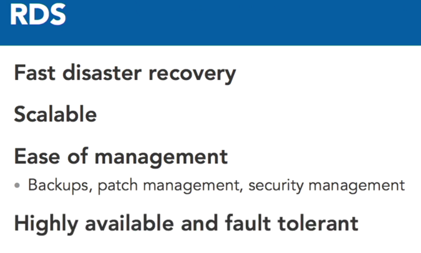
Currently, RDS supports the following engine types, MySQL, Postgres, Aurora, MariaDB, Oracle, and SQL Server.

Design for failure – Lessons
- Fail over gracefully using elastic IPs. Use elastic IPs to quickly remap and fail over to another set of servers so that web traffic is routed to the new servers.This works great for handling emergencies, but also works well for rolling outnew versions of hardware and software.
- Utilize multiple availability zones and even multiple regions if required. Availability zones are conceptually like logical data centers.
- Maintain an Amazon Image so that you can restore and clone environments very easily across multiple availability zones.
- Use Elastic Load Balancing to easily distribute an application across multiple resources and availability zones to ensure it remains up and running even when individual components of the application fail.
- Use Amazon CloudWatch to get more visibility and take appropriate actions in case of hardware failure or performance issues.
- Use EBS to keep persistent data independent of EC2 instances. And take advantage of the portability and power of incremental EBS snapshots to replicate data across availability zones and regions.
EBGP BASIC CONFIG
!!EBGP BASIC CONFIGURATION
!!! (R1) f0/0<—->f0/0 (R2)
!!!!R1
conf t
hostname Emma
no ip domain lookup
line con 0
logg sync
exec-timeout 0 0
exit
int f0/0
ip add 192.168.12.1 255.255.255.0
no shut
int lo 0
ip add 1.1.1.1 255.255.255.0
exit
router bgp 1
neighbor 192.168.12.2 remote-as 2
neighbor 192.168.12.2 password MYPASS
network 1.1.1.0 mask 255.255.255.0
end
sh ip bgp
sh ip route bgp
!!!!R2
conf t
hostname Maria
no ip domain lookup
line con 0
logg sync
exec-timeout 0 0
exit
int f0/0
ip add 192.168.12.2 255.255.255.0
no shut
int lo 0
ip add 2.2.2.2 255.255.255.0
exit
router bgp 2
neighbor 192.168.12.1 remote-as 1
neighbor 192.168.12.1 password MYPASS
network 2.2.2.0 mask 255.255.255.0
end
sh ip bgp
sh ip route bgp
!!EBGP MultiHop CONFIGURATION between R1 and R3
!! Although, having non-BGP router in between is a bad idea
!!! (R1) f0/0<—->f0/0 (R2) fa 0/1 <—-> fa 0/0 (R3)
!!!!R1
conf t
hostname R1
no ip domain lookup
line con 0
logg sync
exec-timeout 0 0
exit
int f0/0
ip add 192.168.12.1 255.255.255.0
no shut
exit
ip route 192.168.23.3 255.255.255.255 192.168.12.2
router bgp 1
neighbor 192.168.23.3 remote-as 3
neighbor 192.168.23.3 disable-connected-check
no neighbor 192.168.23.3 disable-connected-check
neighbor 192.168.23.3 ebgp-multihop 2
end
sh ip bgp neighbors | inc External
!!!!R2
conf t
hostname R2
no ip domain lookup
line con 0
logg sync
exec-timeout 0 0
exit
int f0/0
ip add 192.168.12.2 255.255.255.0
no shut
int f 0/1
ip add 192.168.23.2 255.255.255.0
no shut
exit
!!!!R3
conf t
hostname R3
no ip domain lookup
line con 0
logg sync
exec-timeout 0 0
exit
int f0/0
ip add 192.168.23.3 255.255.255.0
no shut
exit
ip route 192.168.12.1 255.255.255.255 192.168.23.2
router bgp 3
neighbor 192.168.12.1 remote-as 1
neighbor 192.168.12.1 disable-connected-check
no neighbor 192.168.12.1 disable-connected-check
neighbor 192.168.12.1 ebgp-multihop 2
end
sh ip bgp neighbors | inc External
!!Useful sceraio: EBGP MultiHop CONFIGURATION between R1 and R2
!!! lo (R1) f0/0<—->f0/0 (R2) lo
!!! f0/1 <—>f0/1
!!!!R1
conf t
hostname R1
no ip domain lookup
line con 0
logg sync
exec-timeout 0 0
exit
int f0/0
ip add 192.168.12.1 255.255.255.0
no shut
exit
int f0/1
ip add 192.168.21.1 255.255.255.0
no shut
exit
int l0
ip add 1.1.1.1 255.255.255.0
exit
!!!!R2
conf t
hostname R2
no ip domain lookup
line con 0
logg sync
exec-timeout 0 0
exit
int f0/0
ip add 192.168.12.2 255.255.255.0
no shut
exit
int f0/1
ip add 192.168.21.2 255.255.255.0
no shut
exit
int l0
ip add 2.2.2.2 255.255.255.0
exit
Correct me if i am wrong
- I have two phone lines. I am getting ADSL connection from internode using phone line 1 and another ADSL connection on from telstra using phone line
Can I combine the bandwidth for outgoing traffic? i guess no…… OK
Can I do load sharing 50/50 for outgoing traffic? I guess i can use a router with 2 WAN ports and load sharing capability Or I can use two routers having equal metric default route set.
Can I do load sharing say 80/20 for outgoing traffic? I guess no…… need to run BGP for that.
2. What is buffer and queue from routers perspective? if queue is something associated with each interface of router and buffer is the memory segment from RAM of router to store packets? is there is separate buffer for each interface or there is one buffer for whole router? Are queues and buffer created dynamically and can grow/shrink upto certain limit?
Explain it in a congestion scenario? focus on queue and buffer of router.
3. what is ip route 192.168.0.0 0.0.0.0 s0/0 means
4. differencence between rtp and tcp
EIGRP Summaristion
R1 got 3 loopback address and a serial connection to —256K—> r2
R1 —–512k->R3
also, R2 and R3 is connected via gig bit connection.
Task …… summaries 3 to routes of loopback
R1.
- int lo /32 bit address
- create 3 lo intrefaces……..12,32,75 as 3rd octet /24 address
- int serial –> ip add and bandwidth, turn it on
- configure eigrp network 0.0.0.0 (any inteffaces)
summarize
VERIFY
- sh ip eigrp interfaces
Frame Relay
POINT TO POINT
R1 s2/1.1—-102 – 201– R2 10.12.0.0 /24
R1 s2/1.2—–103 – 301–R3 10.13.0.0 /24
Set up frame relay switch
- turn on fr switching
- set interfaces -> encap, intrf-type dce, clock rate, no shu
- create 2 PVCs using connect command
R1
- create loopback interface, ip add
- interface s2/1 –> encapsu, no sh
- point-to-point Sub-interface to support 2 PVCs:
- ip add
- tell dlci to use [1]
- create ospf
R2 and R3
- create loopback int
- int s2/2 -> encap, ip add, no shu
- network type make it point-to-point
- create ospf
60 sec wait
and then check frame-relay map
VERIFICATION
R1 -> sh frame-relay map
show 2 map which are there because of frame-relay interface-dlci statement
try pinging between spokes
Hint
[1] frame-relay interface-dlci 102
Frame Relay
Multipoint
(PVC) R1 ———102 FR 201———R2
(PVC) R1 ———103 FR 301 ———R3
Single subnet 10.123.0.0 /24, using physical interface on Hub and Spoke
SET UP Frame Relay Switch
- Provide ability to R4 acting as FR Switch the ability to do FR switching
- Each of its interface
- must use frame relay encapsulation
- A device to act as FR switch also need to have intf-type dce
- as it is dce we need to specify clock rate
- Turn it on [i left it off and wasted 15 minutes troubleshooting it later]
- Tell frame relay switch about 2 PVC…..[1]
On R1, R2,R3
- Create loopback interface
- an example for share route
- Also can use as source to test ping
- Also give it router-id for easily identifying it, if using OSPF
- serial Interface
- encapsulation
- Ip add
- turn on
- We will use ospf as routing protocol, so we want this interface type to be point to multipoint (is it point-to multipoint broadcast/non-broadcast[6]?? LINK)
–> It is going to advertise the ip add on this interface as 32 bit route
–>spokes will adervtise there interface ip add as 32 bit route
–>Effectively allow Full reachability by these routers on multipoint network
–> without us to do additional static mapping
3. Enable ospf
4. Check ospf network type – what is it[7]?
5. make sure the interface type is point to multipoint
INFO
NOTE: We learned mulipoint networks on frame relay are pain: as we have to disable split horizon on HUB.
Using OSPF and interface network type POINT-TO-MULTIPOINT will alleviate the pain by……. automatically advertising the 32 bit routes on the spokes, so that spokes can reach other spokes because they learn those routes from ospf due to point to multipoint network types
Tweaks
Q1) Make Spoke network types to other then point to multipoint/what it was before. How will spoke will talk to another spoke [2]
Q2) what is the path of traffic from one spoke to another spoke?direct or via Hub? note: that they are all on 1 subnet.
Q3) if we remove ospf and use eigrp instead then what we need to do for full connectivity?[5]
VERIFICATION:
- what mapping R1 knows? how do it know it? note that we haven’t provided any static mapping on R1[3]
2. who are R1 ospf neighbours
3. What mapping R2 and R3 (spoke) knows? Is there is a mapping on R2 to R3’s ip?
4. Will R2 will be able to ping R3? if yes, Why?How is R2 going to send traffic to R3?[4]
HINTS
[1] connect R1-R2 s2/1 102 s2/2 201
[2] frame relay map ip <remote ip> <local dlci>
[3] sh frame-relay map, using inverse ARP
[4] sh ip route shows what router know
[5] split horizon off on Hub, add static mapping on R2(spoke) to reach R3 and vice-versa
[6] broadcast
[7] R1-> pt to point, R2-> non-broadcast, it is a serial link
Ch4 Manupulate Route Updates
2015 CCNP BOOK – Download topology(Lab not completed yet):

I ran the following command in gns3. Need not to set clock rate on serial link in gns3(from memory).
!!R1
conf t
no ip domain lookup
line con 0
logg sync
exec-timeout 0 0
exit
hostname R1
int fa0/1
desc R1 –> R3
ip add 172.16.12.2 255.255.255.0
ipv6 add FE80::2 link-local
ipv6 add 2001:DB8:0:10::2/64
no shut
int f0/0
desc R1 –> R2
ip add 172.16.13.1 255.255.255.0
ipv6 add FE80::1 link-local
ipv6 add 2001:DB8:0:13::1/64
no shut
end
sh int desc
!!R2
conf t
no ip domain lookup
line con 0
logg sync
exec-timeout 0 0
exit
hostname R2
int lo11
ip ospf network point-to-point
exit
int f0/0
desc R2 –> R1
ip add 172.16.13.2 255.255.255.0
ipv6 add FE80::2 link-local
ipv6 add 2001:DB8:0:13::2/64
no shut
exit
int l011
ip add 10.10.11.1 255.255.255.0
ipv6 add FE80::1 link-local
ipv6 add 2001:DB8:10:11::1/64
int l012
ip add 10.10.12.1 255.255.255.0
ipv6 add FE80::1 link-local
ipv6 add 2001:DB8:10:12::1/64
int l013
ip add 10.10.13.1 255.255.255.0
ipv6 add FE80::1 link-local
ipv6 add 2001:DB8:10:13::1/64
int l014
ip add 10.10.14.1 255.255.255.0
ipv6 add FE80::1 link-local
ipv6 add 2001:DB8:10:14::1/64
end
sh int desc
!!R3
conf t
no ip domain lookup
line con 0
logg sync
exec-timeout 0 0
exit
hostname R3
int range l21-24
ip ospf network point-to-pont
exit
int f0/0
desc R3 –> R1
ip add 172.16.12.1 255.255.255.0
ipv6 add FE80::1 link-local
ipv6 add 2001:DB8:0:10::1/64
no shut
exit
int l011
ip add 192.168.11.1 255.255.255.0
ipv6 add FE80::1 link-local
ipv6 add 2001:DB8:0:192::1/64
exit
int s2/0
desc R3 –> R4
ip add 172.16.11.2 255.255.255.0
ipv6 add FE80::2 link-local
ipv6 add 2001:DB8:0:5::2/64
no shut
end
sh int desc
!!R4
conf t
no ip domain lookup
line con 0
logg sync
exec-timeout 0 0
exit
hostname R4
!!int f0/0 is wrong fix applied later
int s2/0
desc R4 –> R3
ip add 172.16.11.1 255.255.255.0
ipv6 add FE80::1 link-local
ipv6 add 2001:DB8:0:5::1/64
no shut
exit
int l021
ip add 172.16.21.1 255.255.255.0
ipv6 add FE80::1 link-local
ipv6 add 2001:DB8:0:1::1/64
int l022
ip add 172.16.22.1 255.255.255.0
ipv6 add FE80::1 link-local
ipv6 add 2001:DB8:0:2::1/64
int l023
ip add 172.16.23.1 255.255.255.0
ipv6 add FE80::1 link-local
ipv6 add 2001:DB8:0:3::1/64
int l024
ip add 172.16.24.1 255.255.255.0
ipv6 add FE80::1 link-local
ipv6 add 2001:DB8:0:4::1/64
end
sh int desc
!!!!#######################Now we concentrate on setting up OSPFv2 10
int range lo21-24
router ospf 10
network 172.168.11.1 0.0.0.0 area 0
network 172.16.0.0 0.0.255.255 area 0
end
sh ip protocols
!!R3
conf t
router ospf 10
network 172.16.11.0 0.0.0.255 area 0
network 172.16.12.0 0.0.0.255 area 0
network 192.168.11.0 0.0.0.255 area 0
end
sh ip protocols
!!R1
conf t
router ospf 10
network 172.16.12.2 0.0.0.0 area 0
end
sh ip protocols
conf t
int f0/1
!! summarize 172.16.20.0 – 23.255
summary-address 172.16.20.0 255.255.252.0
end
sh ip route
Download topology updated with ospfv2 10, ospv3 20, eigrp AS 100, eigrp for IPv6 AS 200 as shown in the diagram.
